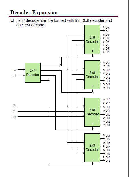
Circuit Diagram Of 3x8 Decoder How To Design A 4 To 16 Decod
3-to-8 line decoder. [diagram] logic diagram 2x4 decoder 74ls126a circuit diagram
74ls126a Circuit Diagram
Decoder in digital electronics 3 to 8 decoder logic diagram Circuit diagram of 8 3 encoder
Circuit diagram of 4 bit decoder
What is 3 to 8 decoder3x8 decoder circuit diagram [diagram] logic diagram of 3 to 8 decoderDecoder ic datasheet pinout logic chip ttl components101 output circuitry mentve.
Decoder encoder octal binary spin qubit quantum computing3-to-8 line decoder. 74ls138 decoder pinout, features, circuit & datasheetDecoder vhdl encoder using 3x8 8x3 ckt write simulate engineersgarage.

Computer organization and architecture (integrated circuits)
Decoder circuit line demux demultiplexer diagram designing3 to 8 line decoder : designing steps & its applications Logic diagram of 3 to 8 decoderHow to design a 4 to 16 decoder using 3 to 8 decoder.
Vhdl tutorial 13: design 3×8 decoder and 8×3 encoder using vhdlWhat is a decoder in logic circuits Input encoder fever upsc gates binary three combinations representing eight each upscfeverDecoder digital electronics diagram truth table block javatpoint.

Circuit diagram of 3x8 decoder
[diagram] java logic diagram3x8 decoder circuit diagram 3 to 8 decoder logic diagramDecoder, 3 to 8 decoder block diagram, truth table, and logic diagram.
Decoder adder 3x8 function multiplexer logic binary inputs outputs block demultiplexer circuits nand designing segment .


3-to-8 line decoder. | Download Scientific Diagram
![[DIAGRAM] Logic Diagram Of 3 To 8 Decoder - MYDIAGRAM.ONLINE](https://i2.wp.com/instrumentationtools.com/wp-content/uploads/2018/09/3-to-8-Line-Decoder-Circuit-Diagram.png)
[DIAGRAM] Logic Diagram Of 3 To 8 Decoder - MYDIAGRAM.ONLINE

3 to 8 decoder logic diagram - Wiring Diagram and Schematics

3x8 Decoder Circuit Diagram

3-to-8 line decoder. | Download Scientific Diagram

Circuit Diagram Of 3x8 Decoder

3 to 8 decoder logic diagram - Wiring Diagram and Schematics

What Is 3 To 8 Decoder

74ls126a Circuit Diagram